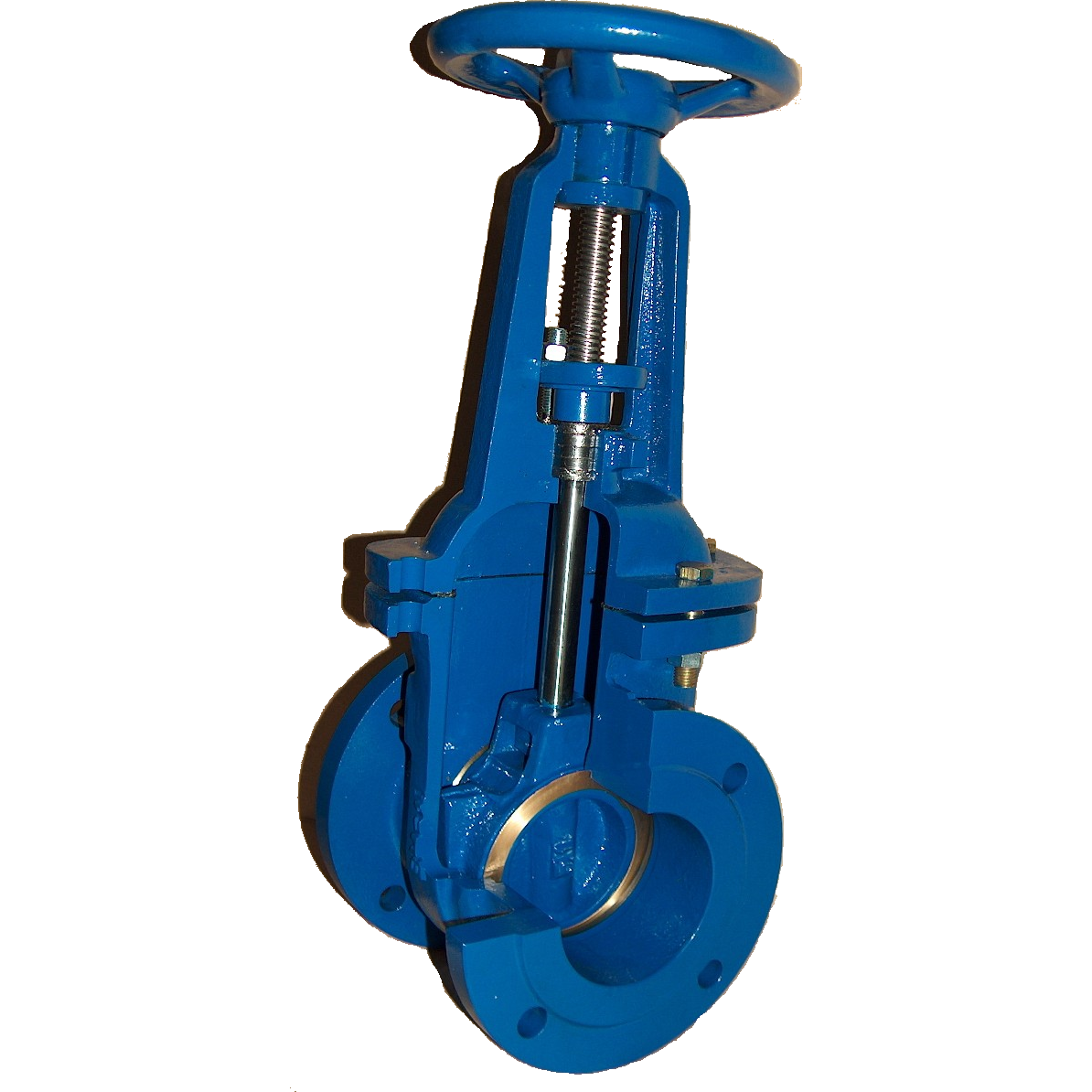
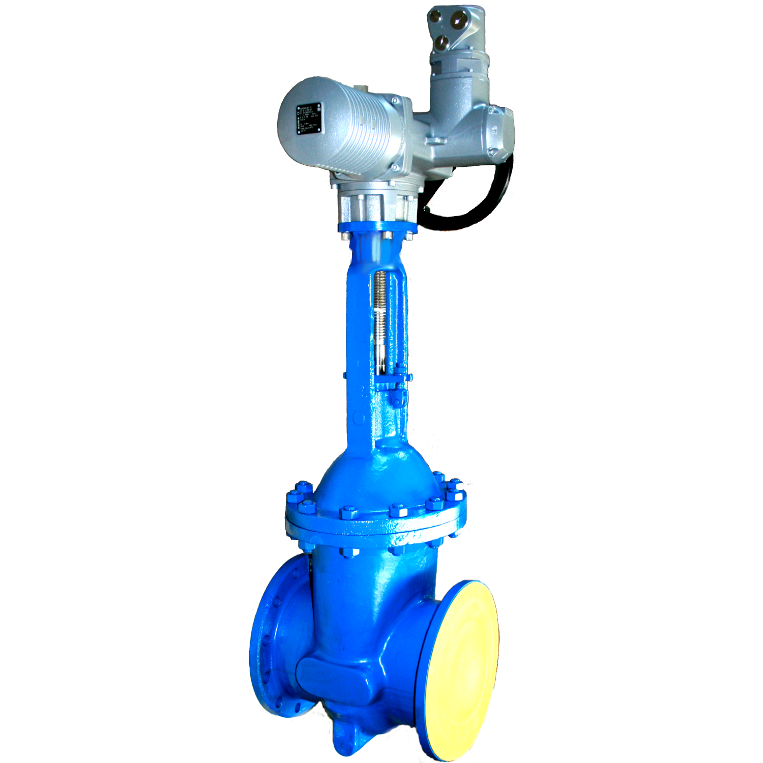
Beschreibung
DN 40 – 500 PN 10 – 250 mit Flanschen oder Anschweißenden
DN 40 – 500 PN 10 – 250 with flanges or welding ends
- -Ausführung nach DIN 3352 Teil 7
basic design according DIN 3352 part 7 - Flanschverbindungen nach DIN 2501 Teil 1 und ISO 7005-1
flanges connecting dimensions according to DIN 2501 part 1 and ISO 7005-1 - Baulängen nach
DIN 3202 Teil 1 Reihe F5 und EN 558-1 Reihe 15 PN 10 – 25
DIN 3202 Teil 1 Reihe F7 und EN 558-1 Reihe 26 PN 40 – 100
face to face according to
DIN 3202 part 1 line F5 and EN 558-1 series 15 for PN 16, PN 25
DIN 3202 part 1 line F7 and EN 558-1 series 26for PN 40 and PN 63 - Mit außenliegender, steigender Spindel aus X 20 Cr 13 (1.4021)
With outside, rising stem of X 20 Cr 13 (1.4021) - Temperaturbereiche -10°C bis 400°C mit Drücken nach DIN 2401 Teil 2 und ISO 7005-1
Temperature range -10°C to 400°C; pressure – temperature ratings according to DIN 2401 part 2 and ISO 7005-1 - Gehäuse, Deckel und Keil aus GP 240 GH (GS-C25)
Body, bonnet and wedge made of GP 240 GH (GS-C25) - Gehäuse- und Keilsitz gepanzert mit 13% Chrom
Body and wedge seat stellited with 13% Chromal - Prüfungen nach ISO 5208 und DIN 3230 Teil 3-BQ,-BN
testing according to ISO 5208 and DIN 3230 part 3-BQ,-BN
Für Heißwasser, Dampf, Kondensat und neutrale Flüssigkeiten sowie Gase
for hot water, steam, condensate and neutral fluids as well as gases

